I keep mentioning that I’m looking for an authentic arcade experience in my custom build. Admittedly, there’s no rhyme or reason to the compromises I’ve decided to make. Since this is my project, I guess whatever makes me happy is all that matters. One of the oddities I insisted on having was a coin meter.
At the time of this writing, my custom build is actually done and I’m catching up on posts I wanted to do. Now that you know that, I can safely say wiring up the coin meter was one of the hardest challenges for me in this project and the last thing to hold me up. I know very little about electrical engineering so I was trying to aquire just enough knowledge to wire in the coin counter. Read a bunch of stuff, try to wire it up and see what happens.
What made this difficult is that my coin meter was a 12 volt meter which I ordered from Twisted Quarter. Those 12 volts are important because the Raspberry Pi runs off five volts. All of the keyboard-emulated buttons — including coin switches — work off the iPac which connects to the Pi via USB; also five volts. So how do you wire up the coin mechs to trip both the 12 volt meter and the five volt coin switch on the iPac without blowing something up?
I’ll spare you the boring stories of what didn’t work and jump right to the solution. The key is to use the ground wire and restrict the voltage flow with Zener diodes.
Here’s what you need:
- Two 1N4007 Zener diodes. I got ten of them from DigiKey for a little over five dollars – that includes the shipping cost.
- Euro-Style terminal connector from DigiKey. A couple of dollars for two.
- 12v six-digit meter with diode. That with diode part is important. This was about six dollars from Twisted Quarter.
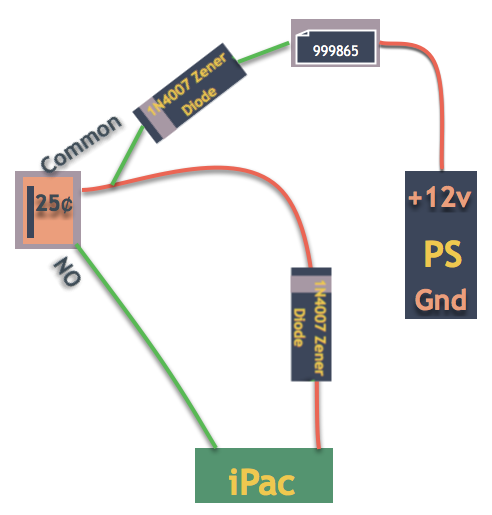
Not a great diagram, but hopefully enough to give you the idea.
Wire +12v from your power supply to the coin meter. Wire the ground from the coin meter needs one of the diodes on it. Splice this ground into another diode and connect that to the (hot) coin switch point on the iPac. A third wire coming off of the splice is what goes to the common line on your coin mech switch. Then run another ground wire of the Normally Open (NO) point on your switch to the ground of the iPac. It’s important that you install the diodes in the correct direction because they prevent the voltage from flowing the wrong way through the circuit. Here’s a non-technical diagram I made up. Apologies if you’re red/green colorblind. Red represents hot wires, and green is ground.
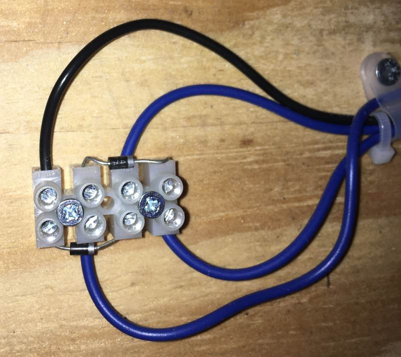
Here's a picture of how I wired in the diodes to the terminal connector. In retrospect, I should have switched up the wire colors here.
Thanks
I would have never been able to do this without help from the community, so thanks to everyone who posted in the following threads:
Comments
classicarcadeprojects